I have it set to mode 4 to control the pump high, pump low and booster pump. Intermatic multipurpose control mechanism model:
Intermatic Timer Wiring Diagram Hanenhuusholli
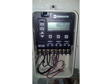
Just for my curiosity, even if both circuit 1 and 2 are on, isn't it not possible for lo and hi are on together because circuit 1 will disconnect hi?

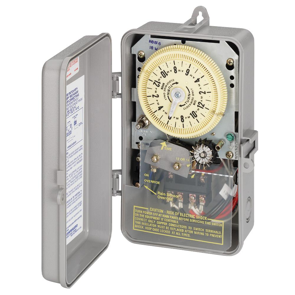
Intermatic p1353me wiring diagram. The most common pool timer used for inground pool pumps is the intermatic time clock. Step 2 open the intermatic timer's cover. I have since replaced them with a single intermatic p1353me 3 circuit timer.
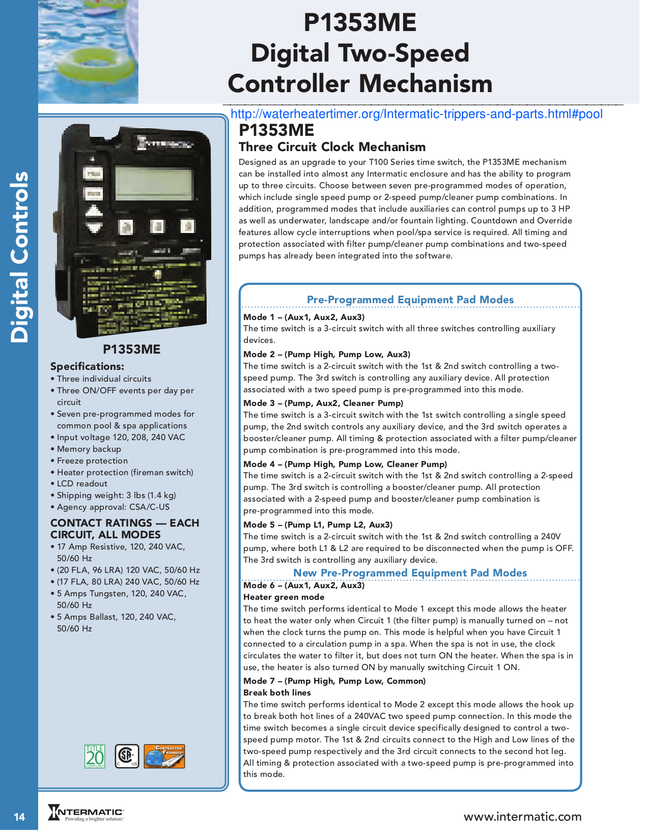
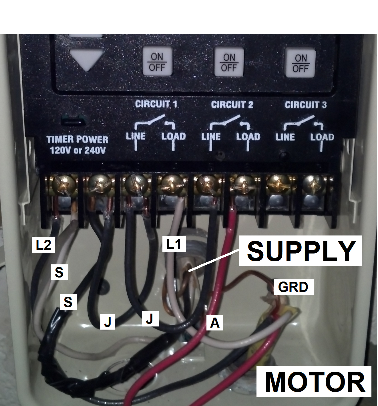
The fireman's switch is not wired into 120 or 240 volts. Failure to comply with instructions could result in personal injury and/or property damage! Intermatic p1353me wiring diagram intermatic p1353me wiring diagram the pme mechanism can be installed into almost any intermatic enclosure and has the ability to program up to three circuits.
Also hook the hot leg of the booster pump through the solar relay so that it can stop the booster pump when priming the panels. Lift or depress, depending on the intermatic timer model, the latch before opening the lid. I will do more research on the timer.
Set the timer to mode #3 and program a cool down time as shown on page 28 of the manual. P1353me 12345 67 attention read carefully before attempting to install your intermatic multifunction control switch. Skoda octavia mk1 wiring diagram pdf.
By iot | february 27, 2020. Hi all, first post here i hope i can help you all out someday. Intermatic pool timer wiring t104r won t turn pump on an wh40 water heater diagram how to connect t101 white ei200w electronic timers instructions operating r8806p101c supplementary p1353me manual wall digital switch t104 off t106r 24 hour dial et1105 outlet in lighting intelliflo vs whisperflo e1020 installation et1705c owner s reviews.
I need help/ schematic in wiring a new intermatic pme and it will be replacing. Open following link for wiring diagrams and manual. When wiring, be sure to follow local and nec/cec electrical codes.
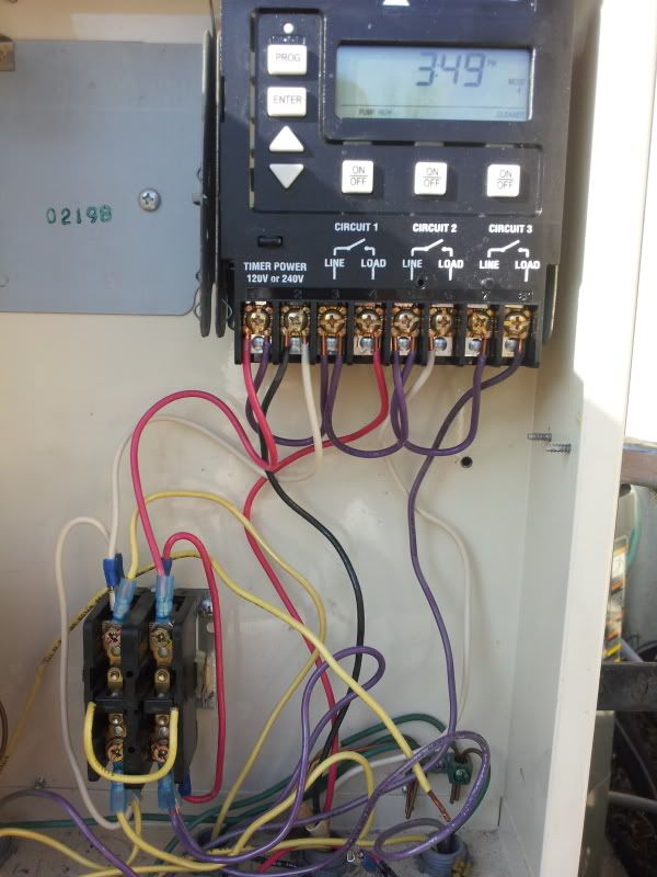
Together with the schematic from the whisperflo, i labeled wiring in the. Guidance needed for wiring of pool pump timer bypass in 240v system diy home improvement forum need help an intermatic wh40 water heater time switch into the doityourself com community forums t104r won t turn on but does it off how. Follow wiring diagram on page 4, connect 240 volt.
The blower is wired directly to 220, i have not hooked up my heater yet and would like to have the heater available to come on when the pump is on high speed only. See rating inside enclosure door (clock not included wiring diagram the new intermatic wired remote control allows. Step 1 turn off the circuit breaker to the appliance that the intermatic timer operates.
Three on/off events per circuit per day. Thread status hello , this is an inactive thread. How to wire p1353me intermatic pool timee
To wire switch follow diagram above. You must log in or register to reply here. Pool pump timer bypass in 240v system intermatic wiring t104 off with heater delay circuit suraielec 7 day basic repair grasslin t104r won t turn on problem what else to do solarattic solar.
Wouldn't it just switch to lo regardless. When this loop is closed, the heater will run. Here's a wiring diagram that should get you what you need.
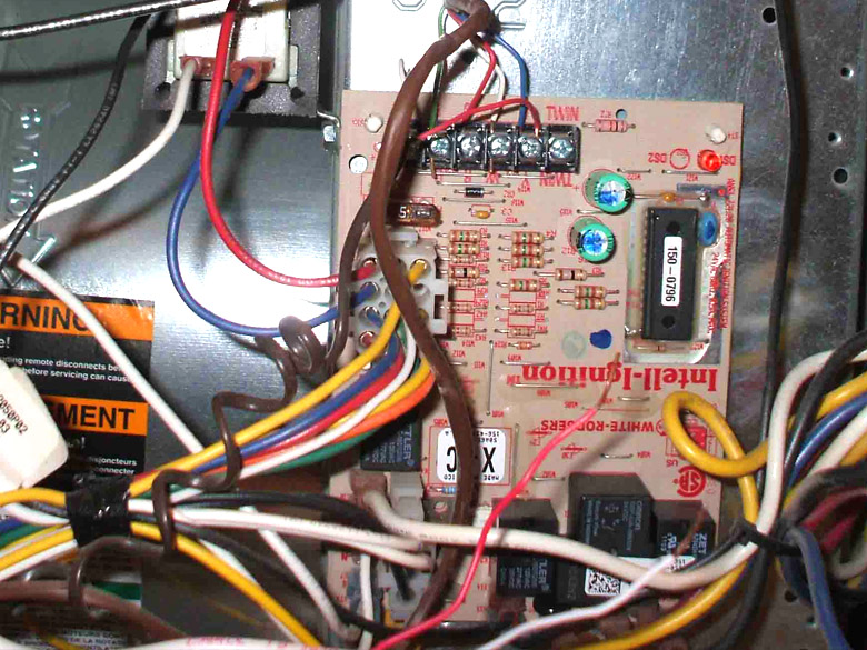
Follow wiring diagram on page 4, connect 240 volt. It basically takes 24 vac from the heater and sends it up one wire, through the fireman's switch and then back to the heater.

Intermatic pool timer manual switch for generator
33 Intermatic Timer Wiring Diagram Wiring Diagram Database
Intermatic Digital Light Timer Instructions Shelly Lighting
Intermatic Digital control centers, parts, manuals

P1353ME wiring question for newbie
Intermatic Timer Wiring Diagram Wiring Diagram

SOLVED Wiring diagrama for timer p1353me Fixya

Download free pdf for Intermatic P1353ME Three Circuit
Wiring a Furnace Overview Mobile Home Repair
[DIAGRAM] Intermatic E10694 Pool Timer Wiring Diagram FULL

PDF manual for Intermatic Other P1353ME Three Circuit Clock

Spa 220 Wiring Diagram

Intermatic ET1125C 24Hour 30Amp Electronic Time Switch
Wiring Diagram For T104 Timer Wiring Diagram Schemas

33 Intermatic Timer Wiring Diagram Wiring Diagram Database
Intermatic P1353me Wiring Diagram

Intermatic P1353me Wiring Diagram
PDF manual for Intermatic Other P1353ME Three Circuit Clock

Intermatic P1353me Wiring Diagram