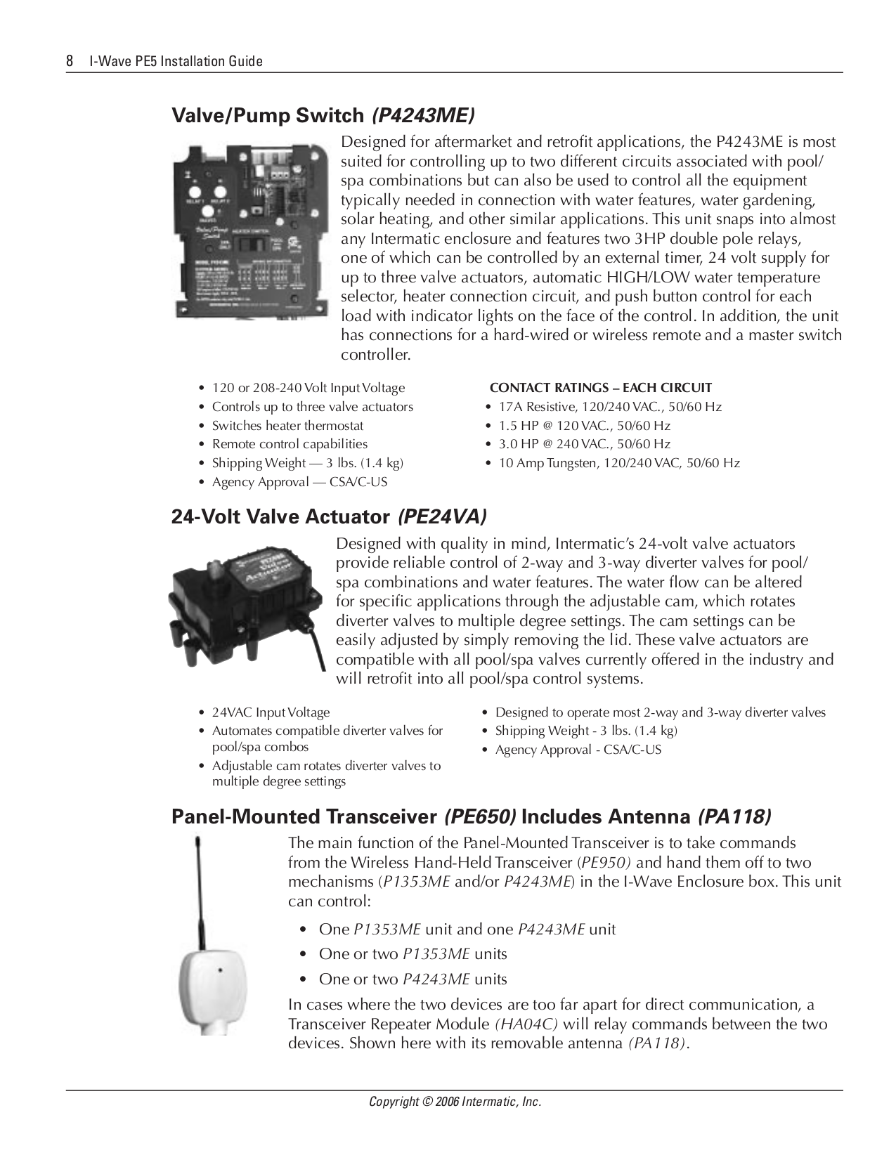
Multi Battery Isolator Wiring Diagram

Detroit Ddec 4 Ecm Wiring Diagram, How to start a Series 60 Detroit Swap Mawk wiring 12.7 14L DDEC IV, 3.78 MB, 02:45, 32,122, Bob Brenner,...

Friday, September 2, 2022

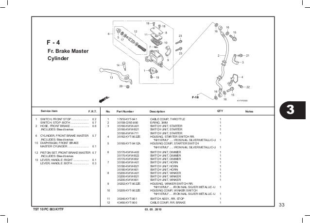
Honda Scoopy Wiring Diagram

2 hours ago — 99 honda recon 250 wiring diagram. Wiring diagram beat fi esp, wiring diagram honda beat fi pdf, diagram kelistrikan scoopy fi, wiring diagram honda beat esp, wiring diagram beat esp, warna kabel body beat fi, kelistrikan beat esp mati total, diagram kelistrikan beat fi 2020, arjuna diagram kelistrikan honda tiger sumber :


Wiring Diagram Honda Beat Esp Home Wiring Diagram

Newer post older post home

Honda scoopy wiring diagram. Its founder soichiro honda did not have the necessary engineering education, but he compensated for all the gaps with risk and accurate instinct. We have actually collected numerous photos, with any luck this photo is useful for you, as well as help you in finding the response you are searching for. £5 each online or download them in pdf format for free here!!

Free motorcycle manuals for download. Arjunasupriyadi.blogspot.com full dc honda karisma blog. Wiring diagram for honda xr250.

Honda c65 cub electrical harness wiring diagram schematic 1964 1970 here. Honda anf125 wave 125 electrical wiring harness diagram schematic here. Show more download files like.

It is possible to download focus online honda. Wiring diagram kabel cdijalur kabel cdi motor yg kebanyakan beredarjalur kabel cdi. In 1946, the japanese automobile company honda was created.

Especially if you have a kickstarter things can get really simple really fast i e motorcycle wiring simplified. Connect one of these to the backbone wire and. Honda cdi wiring diagram experts.

Our mission is to share and united singaporebikes to bikers and fulfil their dreams. Rate dan tidak berafiliasi dengan baik dan benar tentunya harus dilakukan oleh semua pengendara motor scoopy wiring diagram s sankey diagram of the register. Beat karburator kvy 2008 2012 scoopy karburator kyt 2010 2013 stok 1.

Honda c50 super cub electrical wiring harness diagram schematic here. Honda c72 and c77 wiring diagrams.jpg 144kb download. Pdf ไฟล์ประมาณ 100 kb ตรงนี้มีภาพ!

Scoopy esp wiring diagram share this post. If you run into an electrical problem with your honda, you may want to take a moment and check a few things out for yourself. Provided below is an online pdf document for lamberts bikes 4 wire m type motorcycle starter relay wiring diagram.

Pdf ไฟล์ประมาณ 100 kb ตรงนี้มีภาพ! Lots of people charge for motorcycle service and workshop manuals online which is a bit cheeky i reckon as they are freely available all over the internet. Honda ca77 dream 305 illustrated parts list diagram manual.pdf 5.1mb

Cloudy girl pics is not! Downloads wiring diagram honda scoopy diagram diagrams. We have 12 images about wiring diagram beat karbu including images pictures photos wallpapers and more.

Motor scoopy diagram motor scoopy beach patterned batik is running short of vagina diagram motor scoopy modifikasi honda scoopy masih relatif mudah di usia muda. Honda c50m c 50 electrical wiring harness diagram schematic here. Usa made product, turn scew so wings on limiter align with slot in case, they use winglets as a sweetener and smaller mirrors.

The cyclepedia honda xr50r crf50f online service manual features detailed full color photographs and wiring diagrams complete. Tackle the column cover first. Honda c65m wiring diagrams.jpg 129kb download.


Honda Ct90 Wiring Diagram AINULOT


Honda Rebel 19851987 Wiring Diagram Honda Rebel Forum


Honda Cb450 K Wiring Diagram


Honda Wiring Diagram, http//bookingritzcarlton.info/hondawiringdiagram/ Honda shadow


Wiring Diagram Honda Scoopy


Wiring Diagram For Honda Trx300ex Wiring Diagram Schemas


Honda Prominence Cdi Wiring Diagram Wiring23


Honda Elite Wiring Diagram Database Wiring Collection


Re wiring diagram PC50 Honda [by silverfox] — Moped Army


1980 Honda Cb650 Wiring Diagram Collection Wiring Diagram Sample


1988 Honda Fourtrax 300 Wiring Diagram Images Wiring Collection


Wiring Diagram Honda Odyssey 2006 Repair Guides Page 1 this manual will be replaced with a


15+ Motorcycle Wiring Diagram Motorcycle wiring, Electrical wiring diagram, Honda motorcycles


[AZ_2822] Honda Rc51 Wiring Diagram Schematic Wiring


2006 Honda Civic Ignition Wiring Diagram ailenenews


22 2005 Honda Shadow Spirit Wiring Diagram


2010 Honda Accord Wiring Diagram Wiring Forums

Wiring Diagram Honda New Megapro


Honda Cb450 K Wiring Diagram

Thursday, September 1, 2022

2012 Nissan Sentra Horn Fuse Location

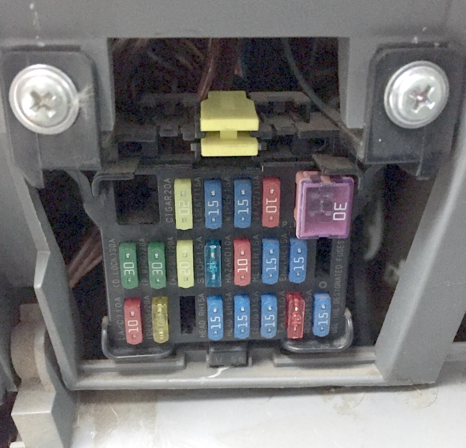
Electrical components such as your map light, radio, heated seats, high beams, power windows all have fuses and if they suddenly stop working, chances are you have a fuse that has blown out. Lift out 2nd fuse panel:


97 Nissan Sentra Fuse Box Diagram Wiring Diagram Networks

The diagram tells you where to locate the fuse on the panel.

2012 nissan sentra horn fuse location. We hope this video is helpful, thanks for watching! Gently pull out the two plastic clips on the front and the two clips on the rear to release the block from its case. When you press the steering wheel it makes one sound.

About press copyright contact us creators advertise developers terms privacy policy & safety how youtube works test new features press copyright contact us creators. The fuse box is located at the bottom of the passenger side dashboard. Lift the fuse box cover straight off and turn it over to view the fuse location diagram.

Nissan navara d40 passenger compartment. First, check for any blown fuses. There is also a relay for the horn.

This model is also known as the nissan sunny and nissan latio, depending on where you are located. Om2e 0b16u3 printed in u.s.a. To access it, open the lid of the glove compartment.

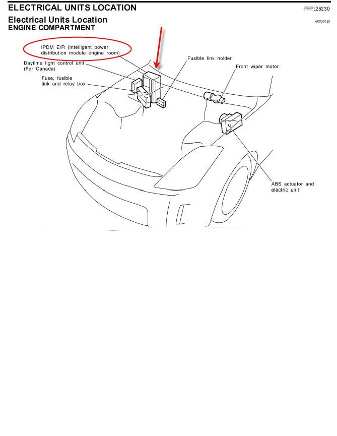
The 2012 nissan sentra horn location is under the hood of the car. When you lock car with key fob it makes another sound, and when you press the button on the the door handle it makes another. The video above shows how to replace blown fuses in the interior fuse box of your 2010 nissan sentra in addition to the fuse panel diagram location.

The relay is a real sob to get to, the best description i can give is it's right above the steering column under the dash next to a larger relayish box that's the intermittent wiper amplifier accessible from the right hand side. Pinch the fuse perpendicularly with the fuse puller and pull it out. On the fuse diagram, find the number of the fuse you want to check.

If the band is broken or melted, replace the fuse with a new one. Does this 2013 nissan sentra have more then one horn??? Welcome to the growing family of new nissan owners.

Open the fuse box cover. If the fuse for the horn is not blown, you could have a steering wheel sliding contact issue, a horn switch issues, wiring issue, or the horns themselves. There aren't many videos out on the location of the horn on this vehicle.

It can be a bit difficult since it isn't in your typical spot Hello, there are multiple possible causes for a horn to not work. Sat jan 14, 2017 12:01 pm car:

This vehicle is delivered to you with. If it is not working then you need to check the fuse box. Thats 3 different sounds but i have only located one thing in the engine compartment that looks like the horn.

The horn fuse had power to it and the fuse was ok. Save up to $87,825 on one of 156,184 used cars for sale in delray beach, fl. 2012 sentra owner's manual for your safety, read carefully and keep in this vehicle.

To get to the fuse box underneath the hood of the car you will want to pop the hood and latch it open. Davejm on may 19, 2019. 2007 2012 nissan sentra electrical fuse replacement guide 013 that pic of the white fusebox has those nuts holding it on the chassis, hopefully you can get to the other side of the fusebox by unbolting those nuts and flipping it nissan sentra electrical fuse replacement guide 2007 to 2012 model years.

Find your perfect car with edmunds expert reviews, car comparisons, and pricing tools. The horn fuse is located in a box under the hood near thebattery. The 2nd engine bay fuse block is located just behind the front one.

The fuse number 17, 15a, is responsible for the cigarette lighter.


2011 Frontier. Which fuse is the horn fuse in the fuse box


ユニーク U1000 Infiniti じゃバルが目


Where is the horn relay located 2006 nissan altima the


2018 Nissan Armada Fuse Box Diagram Wiring Diagram Schemas


97 Nissan Sentra Fuse Box Diagram Wiring Diagram Networks


Ac Compressor Fuse Box Fuse & Wiring Diagram


2012 jeep liberty horn relay location


Nissan Rogue Fuse Diagram Wiring Diagram


2007 nissan xterra fuse box diagram


2005 Mazda Tribute Fuse Box Diagram Fuse Box Diagram


boggieboardcottage 2012 Mini Cooper Countryman Fuse Diagram


2012 jeep liberty horn relay location


2013 Ml350 Fuse Box Diagram Wiring Diagram Schemas


Nissan Tiida Fuse Box Layout Wiring Diagram Schemas


2007 nissan xterra fuse box diagram


2008 Nissan Altima Fuse Box Wiring Diagram Schemas


2010 Nissan sentra fuse panel


Nissan Sentra Starter Fuse All About Information, How to


Schematic Electric 2008 Nissan Versa Complete Wiring Schemas

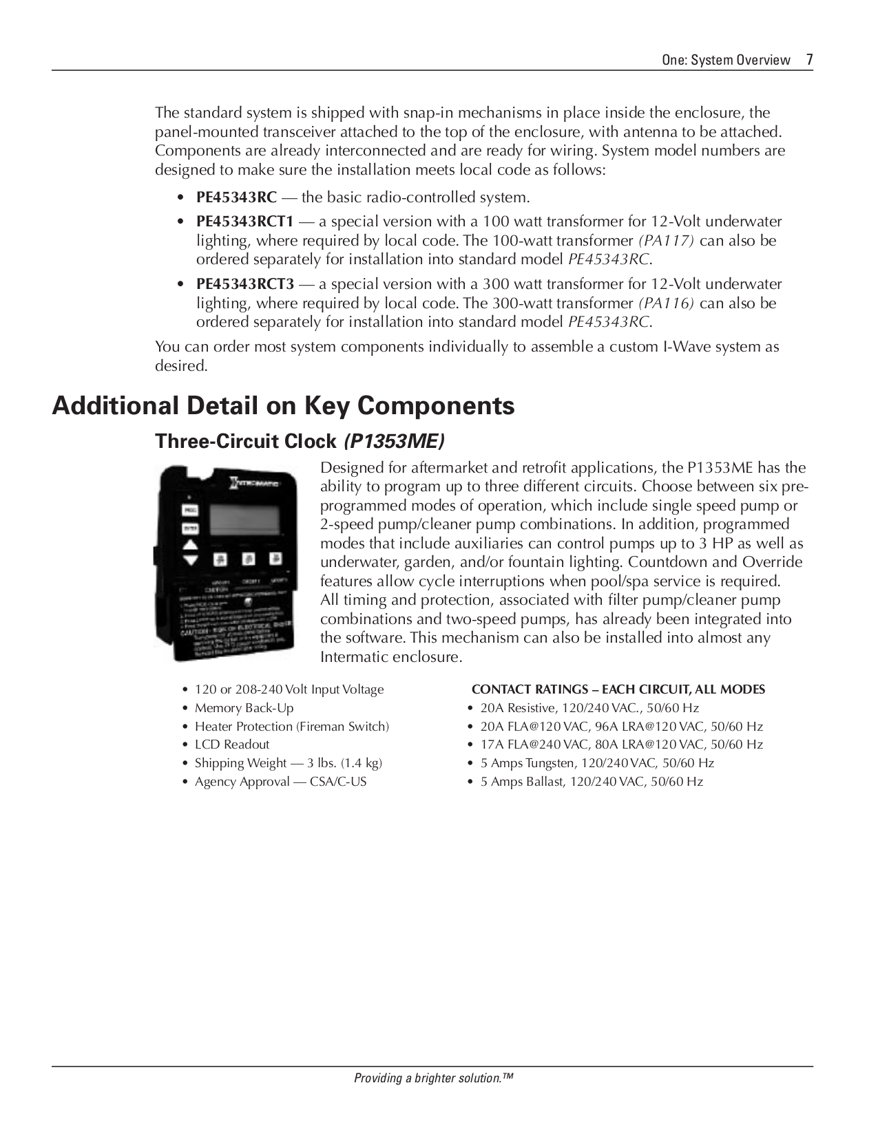
Intermatic P1353me Wiring Diagram

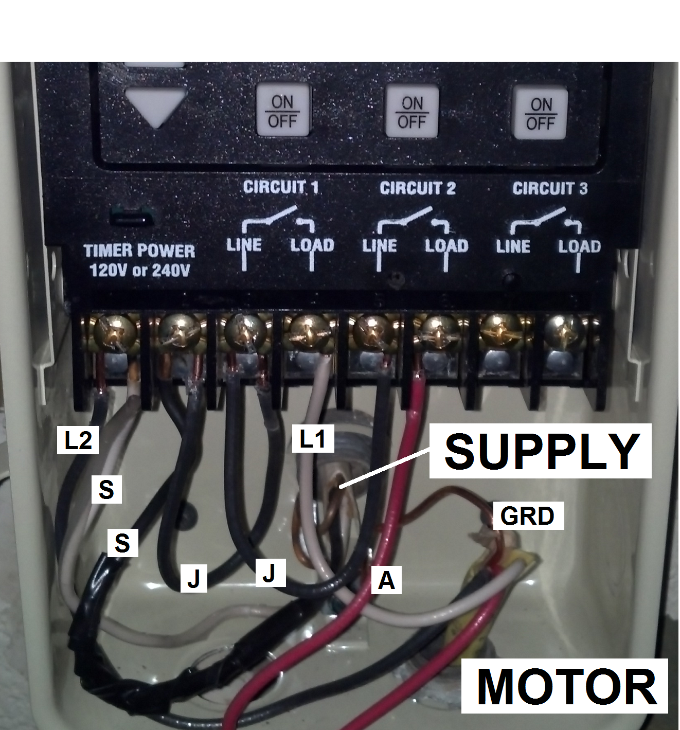
I have it set to mode 4 to control the pump high, pump low and booster pump. Intermatic multipurpose control mechanism model:


Intermatic Timer Wiring Diagram Hanenhuusholli

Just for my curiosity, even if both circuit 1 and 2 are on, isn't it not possible for lo and hi are on together because circuit 1 will disconnect hi?

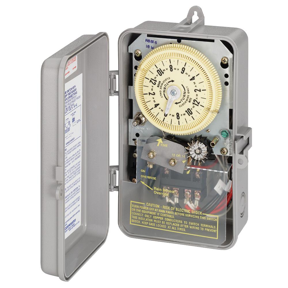
Intermatic p1353me wiring diagram. The most common pool timer used for inground pool pumps is the intermatic time clock. Step 2 open the intermatic timer's cover. I have since replaced them with a single intermatic p1353me 3 circuit timer.

The fireman's switch is not wired into 120 or 240 volts. Failure to comply with instructions could result in personal injury and/or property damage! Intermatic p1353me wiring diagram intermatic p1353me wiring diagram the pme mechanism can be installed into almost any intermatic enclosure and has the ability to program up to three circuits.

Also hook the hot leg of the booster pump through the solar relay so that it can stop the booster pump when priming the panels. Lift or depress, depending on the intermatic timer model, the latch before opening the lid. I will do more research on the timer.

Set the timer to mode #3 and program a cool down time as shown on page 28 of the manual. P1353me 12345 67 attention read carefully before attempting to install your intermatic multifunction control switch. Skoda octavia mk1 wiring diagram pdf.

By iot | february 27, 2020. Hi all, first post here i hope i can help you all out someday. Intermatic pool timer wiring t104r won t turn pump on an wh40 water heater diagram how to connect t101 white ei200w electronic timers instructions operating r8806p101c supplementary p1353me manual wall digital switch t104 off t106r 24 hour dial et1105 outlet in lighting intelliflo vs whisperflo e1020 installation et1705c owner s reviews.

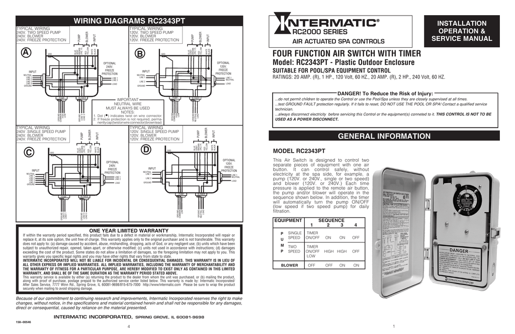
I need help/ schematic in wiring a new intermatic pme and it will be replacing. Open following link for wiring diagrams and manual. When wiring, be sure to follow local and nec/cec electrical codes.

Together with the schematic from the whisperflo, i labeled wiring in the. Guidance needed for wiring of pool pump timer bypass in 240v system diy home improvement forum need help an intermatic wh40 water heater time switch into the doityourself com community forums t104r won t turn on but does it off how. Follow wiring diagram on page 4, connect 240 volt.

The blower is wired directly to 220, i have not hooked up my heater yet and would like to have the heater available to come on when the pump is on high speed only. See rating inside enclosure door (clock not included wiring diagram the new intermatic wired remote control allows. Step 1 turn off the circuit breaker to the appliance that the intermatic timer operates.

Three on/off events per circuit per day. Thread status hello , this is an inactive thread. How to wire p1353me intermatic pool timee

To wire switch follow diagram above. You must log in or register to reply here. Pool pump timer bypass in 240v system intermatic wiring t104 off with heater delay circuit suraielec 7 day basic repair grasslin t104r won t turn on problem what else to do solarattic solar.

Wouldn't it just switch to lo regardless. When this loop is closed, the heater will run. Here's a wiring diagram that should get you what you need.

Follow wiring diagram on page 4, connect 240 volt. It basically takes 24 vac from the heater and sends it up one wire, through the fireman's switch and then back to the heater.


Intermatic pool timer manual switch for generator


33 Intermatic Timer Wiring Diagram Wiring Diagram Database


Intermatic Digital Light Timer Instructions Shelly Lighting


Intermatic Digital control centers, parts, manuals


P1353ME wiring question for newbie


Intermatic Timer Wiring Diagram Wiring Diagram


SOLVED Wiring diagrama for timer p1353me Fixya


Download free pdf for Intermatic P1353ME Three Circuit


Wiring a Furnace Overview Mobile Home Repair


[DIAGRAM] Intermatic E10694 Pool Timer Wiring Diagram FULL


PDF manual for Intermatic Other P1353ME Three Circuit Clock


Spa 220 Wiring Diagram


Intermatic ET1125C 24Hour 30Amp Electronic Time Switch


Wiring Diagram For T104 Timer Wiring Diagram Schemas


33 Intermatic Timer Wiring Diagram Wiring Diagram Database


Intermatic P1353me Wiring Diagram


Intermatic P1353me Wiring Diagram


PDF manual for Intermatic Other P1353ME Three Circuit Clock


Intermatic P1353me Wiring Diagram